Antenna simulation workbench · openEMS FDTD
Design antennas. See the fields.
Fairbeam is a free, open-source desktop app for antennas, microstrip circuits and arrays. Model them in a parametric 3D designer, simulate with the openEMS FDTD solver on the CPU or the GPU, and read S-parameters, far fields and surface currents next to the model.
For macOS (Apple silicon) and Windows. The browser demo opens 19 simulated example projects, read-only.
How it works
From a model to fields, in one patch antenna
Model it
Draw it in the designer, where every length is an expression over named parameters, or import a CST-compatible VBA macro. The same model can also be one Python file with a
build()that places metal, dielectrics and ports.def build(p): sim = Simulation(1e9, 3e9) sim.metal("patch").AddBox(...) sim.dielectric("substrate", 3.38).AddBox(...) sim.lumped_port(1, 50, ...) return simModel geometry
The viewer reconstructs the model geometry: a 32 × 40 mm patch on a 1.524 mm substrate with εr 3.38, a ground plane and a 50 Ω probe feed.
Meshed for FDTD
Fine cells at patch edges and in the substrate, coarser cells in air: 69 × 69 × 58 mesh lines, about 264 k cells.
Excited, the currents flow
A Gaussian-derivative pulse excites the patch. The recorded surface current is strongest near the middle and decreases toward the radiating edges, consistent with the fundamental patch mode.
It radiates
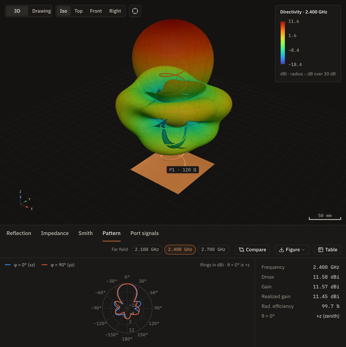
Near-to-far-field transform: 6.79 dBi broadside at 2.453 GHz, 96.5 % radiation efficiency. Radius and color both show directivity.
Checked, then exported
The recorded |S11| minimum is −34.5 dB at 2.4525 GHz. The resonance is about 0.1% below the finer-mesh value of 2.4550 GHz. Export the model, Touchstone data, drawings, a report and preview fabrication files.
Arrays
Four patches, one beam you can steer
One patch becomes four
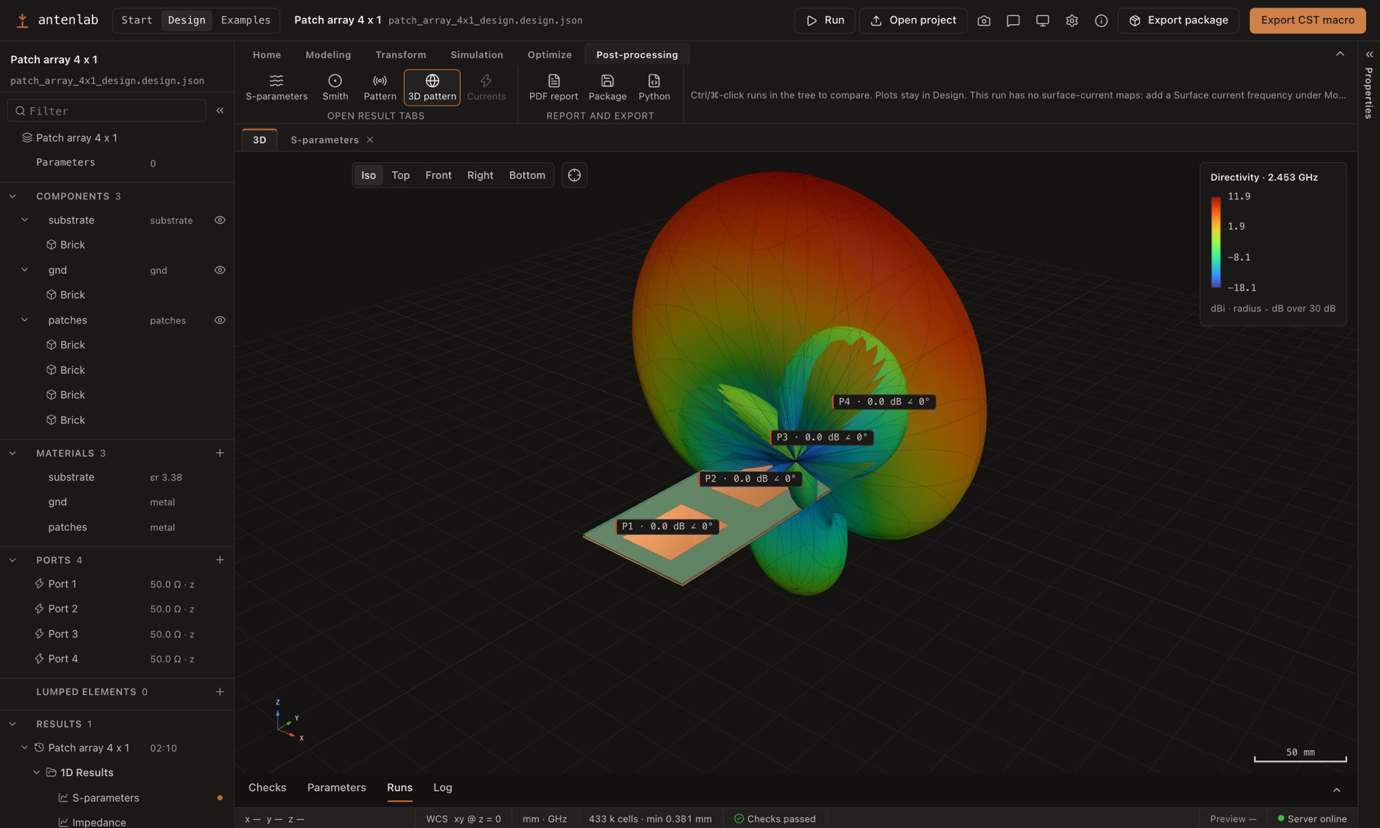
The same patch four times, half a wavelength apart (61.2 mm) on one 66 × 243.6 mm board, each with its own 50 Ω port. Fed in phase they reach 11.9 dBi broadside, about 5 dB above the single patch.
Steered by phase alone
A phase that falls by k·d·sin θ0 from port to port turns the beam. Each angle is the weighted sum of four embedded element patterns from four openEMS runs, so coupling is included and each port's active reflection moves with the beam.
Your turn
Steer the beam using valid amplitude and phase weights at a recorded frequency, and export the combined pattern.
The designer
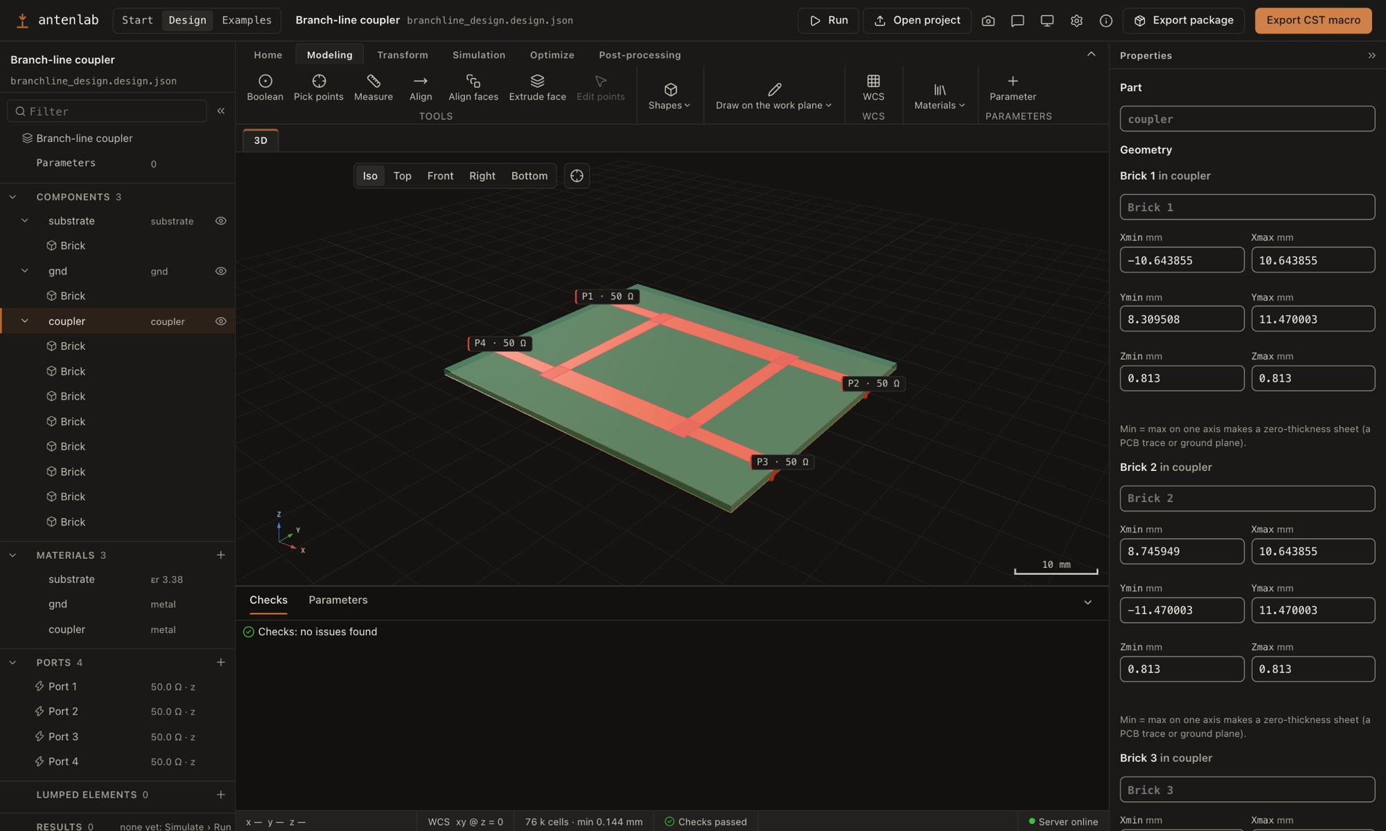
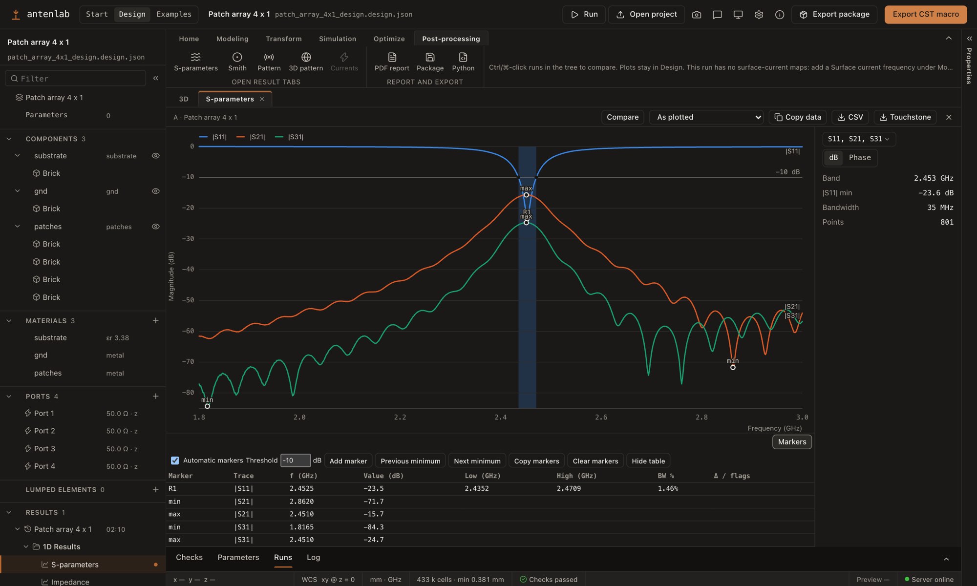
Model, simulate and read the results in one window
Features
What Fairbeam does
-
Parametric 3D designer
Bricks, cylinders, polygons, wires, extrusions and booleans on a one-row ribbon. Every length is an expression over named parameters.
-
openEMS on the CPU or the GPU
Optional Metal and CUDA engines are available. In the documented patch benchmark, solver time was 1.6 s on Metal and 10.6 s on a four-thread CPU build on an M5 Pro; times depend on the model and runtime.
-
Results beside the model
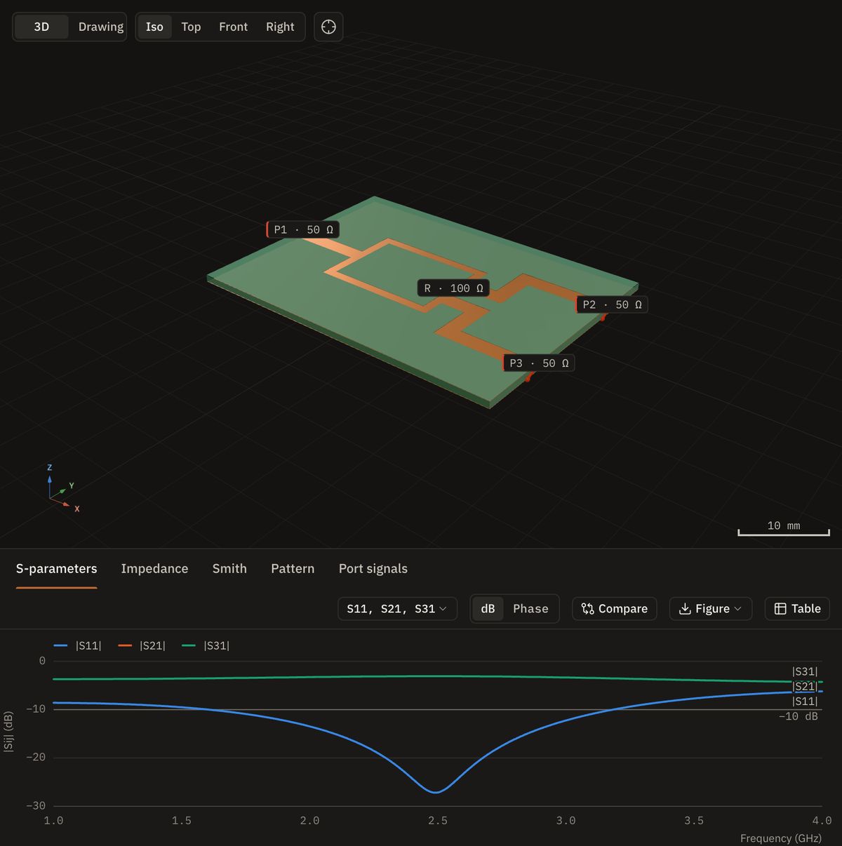
S-parameters with markers, Smith chart, impedance, VSWR, 3D patterns, field maps and animated surface currents.
-
Circuits and arrays
Full S-matrices of filters, dividers and couplers, and array beams steered after the run.
-
Sweeps and an optimizer
Sweeps over up to six parameters, and an optimizer that tunes any number of them towards your goals.
-
Import and export
CST-compatible VBA macros and PCB artwork in; Touchstone, CST-compatible VBA macros, drawings, a PDF report and Gerber files out.
Examples
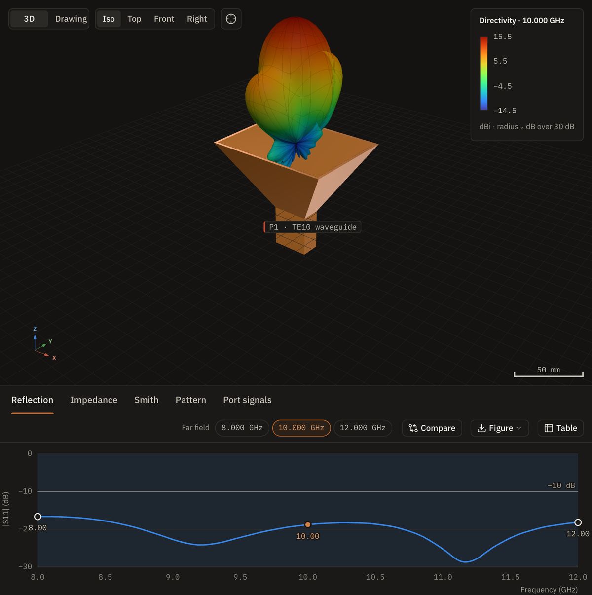
Horns, helices, fractals and circuits
19 simulated projects come with the app and are listed in the browser demo.
Download
Download Fairbeam
Free for macOS and Windows. First-time setup downloads Python, openEMS and dependencies for your user account without admin rights. Estimated download: about 120–155 MB; installed size is larger. Setup and updates need internet access.
New here? Read the getting-started guide: install the app, create a patch antenna, run it and inspect the results.
- The macOS app is signed with a Developer ID and notarized by Apple.
- The Windows installer is not code-signed. If SmartScreen warns, choose More info › Run anyway.
- Checksums are in SHA256SUMS.txt (opens in a new tab). Every version is on the releases page (opens in a new tab). Later versions are offered in the app.
- Linux: no installer yet. Run Fairbeam from the repository (opens in a new tab). To build it from source, see Running Fairbeam from source (opens in a new tab).
About Fairbeam
Fairbeam is an independent open-source project for engineers, researchers and students working with antennas and RF circuits. It brings modeling, openEMS simulation and documented results into one workspace.
Maintained by İsmail Akdağ (opens in a new tab), with contributions from Cem Göçen (opens in a new tab) and the open-source community. Project credits (opens in a new tab).
Contact: ismail@fairbeam.org · Report a problem (opens in a new tab)